Projects id Optical Fiber Fusion Splicers for Increasing Data Traffic A way to become a global leader
Path of a Pioneer in Fusion Splicers Optical network construction required reduced splice loss
Reliable communication quality was required
An arc discharge is a class of gas discharge, in which two electrodes and the gas between them reach a high temperature and emit strong light, as used in welding and other applications. A fusion splicer is a device that joins the ends of optical fibers placed on the right and left instantaneously by melting the ends with heat of approximately 1,800°C generated by an arc discharge.
The fibers used for optical communications are made of silica glass. The inner part of the fiber has a central core and a layer known as cladding around the core. They are arranged in a concentric form. Optical signals entering the core propagate through the core, being repeatedly reflected at the interface between the core and the cladding. Furthermore, optical fibers are divided into two types: single-mode fiber (SMF) and multi-mode fiber (MMF) with a thin core and a thick core, respectively, through which light passes. The core of an SMF is extremely thin, at 9.2 µm (0.0092 mm) in diameter. It reduces attenuation to a minimum using a single mode of propagation for optical signals and is suitable for high-speed, long-distance transmission. In contrast, the core of an MMF is 50 or 62 µm in diameter. The transmission of optical signals in more than one mode is subject to lags in signal arrival time, possibly impairing the normal operation of electronic devices. Being unsuitable for high-speed long-distance transmissions, MMFs are generally used in optical cables on premises. One challenge associated constantly with these optical fibers has been attenuation. When light goes through an optical fiber, the light partly scatters from the optical fiber or generates slight lags in transmission speed due to the use of different wavelengths, causing attenuation (transmission loss). While the Sumitomo Electric Group has delivered world-class low-transmission-loss optical fibers, reduction of splice loss that occurs when connecting optical fibers was also required to construct high-speed and highly reliable optical communication networks.
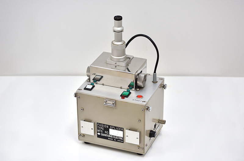
TYPE-3
Splicing optical fiber ends in order of submicrons
Fusion splicing joins the ends of cores through which light is transmitted. Currently, the fiber most popularly used for optical network communications is the aforementioned SMF. Its core is 9.2 µm (0.0092 mm) in diameter. Such very thin cores must be correctly aligned for splicing. If a misalignment or angular deflection occurs between the light axes of two optical fibers, or a gap is created between the ends of the optical fibers, the result is a splice loss due to reflections attributable to a difference in the refractive index between the optical fiber and air. For example, a slight axial deviation of 1 µm (0.001 mm) causes a splice loss of 0.2 dB. Therefore, it is necessary to join the ends of optical fibers with submicron precision. Reducing splice loss was a significant challenge. The Sumitomo Electric Group overcame various technical challenges and, in 1980, launched its first fusion splicer, the MMF fusion splicer (TYPE-3). Using this fusion splicer, the operator spliced optical fibers while looking into a microscope for direct observation of the peripheral positions of the optical fibers. Thus with large-core-diameter MMFs, it was possible to reduce splice loss, although this depended on the operator’s skill and proficiency. Meanwhile to deal with SMFs with a core diameter about one-fifth that of MMFs, in 1982, the Group developed a fusion splicer (TYPE-11) that performed optical fiber alignment. This fusion splicer carried out fusion splicing by placing a light source at one end of an optical fiber, opposite to the splice, and a photoreceptor at one end of the other fiber, and aligning the cores to maximize the amount of light received. However, there still remained many challenges, such as the troublesome work of placing a light source and a photoreceptor at locations several hundred meters to several kilometers away from each other and the amount of time required for splicing.

Development of core-aligning fusion splicers of the direct-core-monitoring type
The Sumitomo Electric Group’s development team produced a direct-core-monitoring technology to observe the optical fiber cores with a microscope and to automatically align them. In 1984, a fusion splicer (TYPE-33) was launched, featuring the technology that allowed for directly observing optical fiber cores with a microscope equipped with a high-resolution, high-powered objective lens. Moreover, the image-capturing system of TYPE-34 incorporated a CCD camera. This technology enabled observation of the optical fiber cores and self-alignment of the cores. However, there were still challenges to be addressed. At the time, soon after joining the Company, Toshihiko Honma, current Department Manager of the Mechatronics Department, Lightwave Network Products Division, worked on the development of the fusion splicer.
“At the time, fusion splicers were increasing in both weight and volume, incorporating components such as a CCD camera, control circuits and a monitor for image processing. As optical fibers came into wider use, fiber installation work began to take place in various environments. As such, there was a rise in demand for superb compact and light fusion splicers. The Group developed smaller and lighter fusion splicers, using small image sensors typified by CMOS,*1 application-specific LSI*2 and multilayer high-density wiring boards. At the same time, to fulfill the growing need for fusion splicers usable in locations where AC power was unavailable (e.g. manholes and elevated sites), in the late 1990s, the Group developed battery-powered models. In 2000 and subsequent years, small, light and battery-equipped fusion splicers went mainstream. Moreover, around that time, with the increasing proliferation of optical fibers on a global scale, the fundamental features incorporated in today’s fusion splicers were achieved, including improved environmental resistance (wind and shock resistance) adapted to harsh outdoor installation work in Japan and abroad. Additionally, maintenance services and accessories vital for fusion splicing, such as cutters and protective sleeves, were fully improved. These items were made possible by the Sumitomo Electric Group’s materials technologies. The FC-8R cutter incorporating the Group’s proprietary self-rotating blade technology holds the largest share in the global market,” says Honma.
*1 Complementary metal–oxide semiconductor
*2 Large scale integration
In the 1980s and 1990s, the aforementioned process of fusion splicer development took place often as a joint project between Sumitomo Electric and its competitors, with participation by a telecommunications carrier. A phase of harsh competition in terms of development began after the turn of the millennium. Thereafter, the Sumitomo Electric Group’s original technologies led the evolution of fusion splicers.
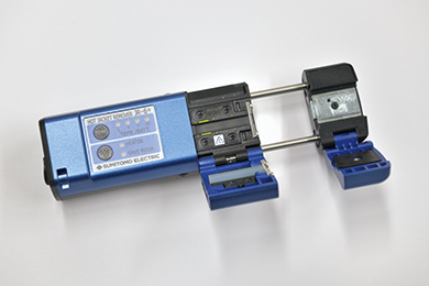
JR-6+
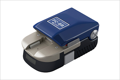
FC-8R